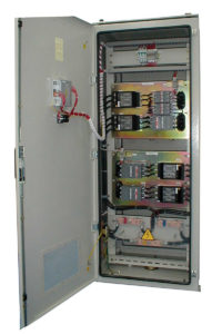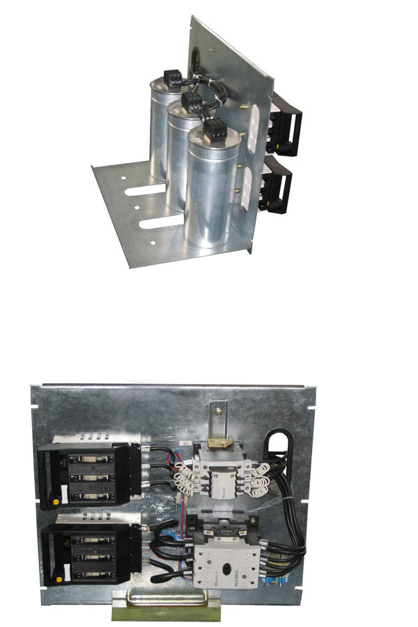
The equipment is used to compensate reactive energy for consumers in the low voltage grid.
Components:
- metallic box / metallic cabinet made in Automatica with electrostatic field painting;
- module-based metallic system made in Automatica;
- dry three-phased capacitors, protection for internal and self-scaring over voltages;
- automated controller with 3, 6 or 12 steps (optionally with serial outlet RS485);
- three-phased contactors;
- fuse-disconnectors for overload and short-circuit protection;
- miniature automatic circuit-breaker for the protection of the controller’s inputs;
- switch for the controller’s command circuit;
- main circuit-breaker (on demand).
Constructively, the versions of Automatica equipment are:
- – compensation modules;
- – reactive power compensation systems in metallic boxes;
- – reactive power compensation systems in module-based metallic cabinets.
The reactive power compensation modules without metallic enclosure can be made up to compensation values of 200 kVAR. These can be installed in cabinets already existing at the beneficiary and can be used as extensions to other compensation systems.
The reactive power compensation systems in mounted metallic boxes can be executed for reactive power compensation values between 12,5 … 100 kVAR.
The reactive power compensation systems in metallic cabinets are made in module-based design and they are executed for reactive power values between 125 … 400 kVAR.

The system offers a series of advantages:
- reduced power bill;
- decreased active power consumption with app. 15%;
- investment amortization in 6-12 months at most;
- increase of the available active power in the transformer’s secondary circuit;
- reduction of the active power losses in the beneficiary’s installations;
- improvement of the local voltage level, thus allowing the power users to operate at rated voltage, with maximum yield.
SC Automatica SA can perform, at the beneficiary’s request, the installment of the reactive power compensation systems.
Technical data
| Standards and specifications |
IEC 60439-1 |
|||
|
IEC 831-1,2 |
||||
| Rated insulation voltage Ui |
630 V |
|||
| Rated operational voltage Ue |
400 V |
|||
| Overvoltage category |
III |
|||
| Pollution degree |
3 |
|||
| Rated frequency |
50 Hz |
|||
| No. of setting steps |
Max. 12 with automated switch |
|||
| Rated power |
12,5 …. 400 kVAR |
|||
| Automatic C/k setting |
from 0,07 A to 1 A |
|||
| Power factor setting |
from 0,9 capacitive to 0,7 inductive |
|||
| Total capacitors losses |
< 0,5 W/VAR |
|||
| Total installation losses |
< 1,5 W/VAR |
|||
| Dielectric losses |
< 0,2 W/VAR |
|||
| Protection degree |
IP 42 ; upon request IP 54 |
|||
| Surfaces treatment |
powder coating |
|||
| Dimensions * |
QN (kVar) |
H |
W |
D |
|
12,5 – 75 |
815 |
615 |
400 |
|
|
100 |
1215 |
650 |
400 |
|
|
100 – 200 |
1500 |
650 |
400 |
|
|
225 – 300 |
2000 |
950 |
400 |
|
|
325 – 400 |
2300 |
950 |
400 |
|
| Operating conditions | ||||
| Climatic protection |
N3, T3, N1, T1 |
|||
| Mounting place |
Indoor, outdoor |
|||
| Ambient temperature |
-10OC … +50OC for operation |
|||
|
-10OC … +55OC for transportation |
||||
| Relative humidity at 20OC |
90% |
|||
*other dimensions per request
