Industrial consumers, in general, pay monthly for a quantity of reactive energy representing the difference between the measured reactive energy and the calculated reactive energy, corresponding to the neutral power factor (0,92).
In order to eliminate these expenses, the improvement of the power factor is done through the injection of capacitive reactive energy in the consumer’s distribution network.
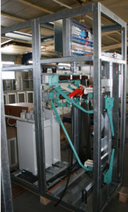
Control systems are used with ecological capacitor banks of fixed value or sequential, installed at the level of 6, 10 or 20 kV, indoor or outdoor.
Each power factor correction switchgear is equipped with exhaust hatches in case of internal incidents (arc fault, capacitors’ defects).

|
Technical data |
Measurement unit |
Nominal values |
| Rated voltage |
kV |
6,3 |
| Frequency |
Hz |
50 |
| Withstand voltage 1 min. at 50 Hz |
kV |
28 |
| Power allowance |
– |
-5%….+10% |
| Discharge time up to 75 V |
S |
600 max |
| Losses |
w/kVar |
0,3 |
| Operating temperature |
– |
-10oC….+40oC |
| Standards |
– |
IEC 60871-1 EN 60871-1 |
The capacitor banks in each switchgear are powered through a three-pole disconnector, with fuses and circuit breaker, when you require a manual actuation, or through a fuse contactor when you require an automated (sequenced) actuation, each sequence having circuit breaker.
